Reverse Osmosis System Parts: A Simple Guide

If your reverse osmosis (RO) system isn’t producing clean water as efficiently as it once did, the problem likely lies in one of its core components. A reverse osmosis system is more than just a filter. It’s a precision-engineered network of parts working together to remove up to 99% of dissolved solids, chemicals, and contaminants from your drinking water. Understanding the parts of a reverse osmosis system is essential for proper installation, maintenance, and troubleshooting.
From the semi-permeable membrane at the heart of filtration to the storage tank that delivers water on demand, each component plays a vital role. In this guide, you’ll learn what every part does, how they interact, and when to replace or service them. This ensures your RO system runs efficiently for years.
Core Filtration Components
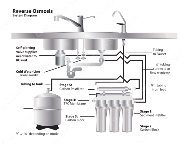
The foundation of any reverse osmosis system lies in its ability to filter water through multiple stages. These stages rely on physical barriers, chemical absorption, and selective membranes to purify water. Without these core parts functioning correctly, even the most advanced system will fail.
Reverse Osmosis Membrane Function
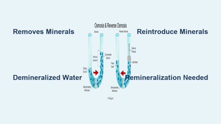
The RO membrane is the system’s most critical component. It uses a thin film composite (TFC) semi-permeable barrier to reject dissolved solids like salts, heavy metals, fluoride, and nitrates. Water is forced through this dense membrane under pressure, while contaminants are flushed to the drain.
Membranes are rated by gallons per day (GPD). Common sizes include 50 GPD and 75 GPD for residential use. Higher GPD ratings require matched flow restrictors to maintain optimal pressure. A drop in performance, measured by rising TDS (Total Dissolved Solids) levels, signals it’s time for replacement, typically every 3–5 years.
Sediment and Carbon Pre-Filters
Before water reaches the membrane, it passes through sediment and carbon pre-filters. The 5-micron sediment filter captures rust, sand, and silt that could clog the system. Next, the carbon block filter removes chlorine, chloramines, pesticides, and volatile organic compounds (VOCs), protecting the sensitive RO membrane from damage.
Some systems use chloramine-specific carbon blocks for municipal water supplies. These filters should be replaced every 6–12 months. Failing to do so shortens membrane life and reduces water quality.
Post-Filtration Polishing Stage
After passing through the membrane, purified water flows through a post-carbon filter for final polishing. This stage eliminates any remaining tastes or odors that may develop in the storage tank. It ensures the water tastes fresh and clean when dispensed.
Some advanced systems include inline granular activated carbon (GAC) filters or specialty media like bone char for fluoride reduction. Replacing this filter annually maintains peak taste and odor removal.
Filter Housing and Installation
Housings secure the filters and membrane in place while maintaining pressure integrity. They’re not just containers. They’re engineered components designed to handle specific flow rates and pressures.
Standard Filter Housing Types
Most residential RO systems use 2.5″ x 10″ sump housings for sediment and carbon filters. These plastic housings screw onto mounting brackets and connect via 1/4″ NPT threaded ports. They come in white or black and are compatible with standard filter cartridges.
Always lubricate the O-ring with food-grade silicone grease (NSF-61 certified) before installation to prevent leaks and extend seal life. Never use petroleum-based lubricants like Vaseline, as they degrade rubber O-rings.
Membrane Housing Design
The membrane housing is smaller and built for high-pressure operation. It holds the 1812-size membrane (11.75″ long, 1.75″ diameter) and features 1/8″ NPT ports to match the lower flow rate of the RO stage. This housing connects directly to the automatic shutoff valve and drain line.
It’s secured with a membrane clip and two #10 screws (one 1″ long if the clip is used). Proper alignment ensures no leaks during operation.
Mounting Brackets and Clips
All housings and the membrane must be securely mounted under the sink. Plastic or metal brackets hold components in place using #10 screws. A filter-to-membrane clip can attach a post-filter directly to the membrane housing, saving space.
For larger systems, Big Blue housings (4.5″ diameter) may require a heavy-duty Big Blue wrench for removal. Ensure all units are accessible for future maintenance.
Water Flow and Pressure Control
RO systems rely on precise water flow and pressure balance. Too little pressure reduces output. Too much can damage components. Hydraulic control parts ensure the system operates efficiently and safely.
How Automatic Shutoff Valves Work
The automatic shutoff valve (ASO) stops feed water when the storage tank is full. When tank pressure reaches about 65% of incoming line pressure, the ASO closes, preventing continuous drain flow.
Two common types exist: horseshoe flow (U-shaped path) and straight-through flow. Both use 1/4″ quick-connect fittings. A failed ASO causes constant draining. Replace it immediately to avoid water waste and pressure loss.
Flow Restrictor Sizing Guide
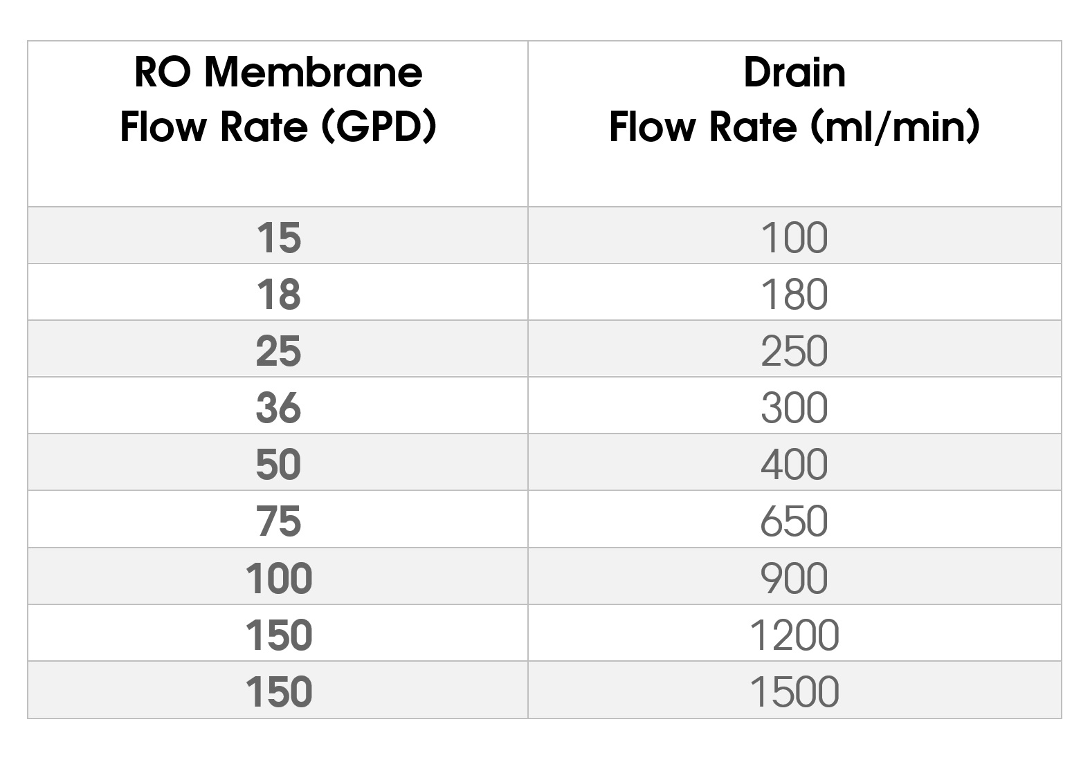
The flow restrictor controls how much water goes to the drain, creating backpressure that forces water through the membrane. It must match the membrane’s GPD rating:
• 18 GPD → 150 ml/m
• 50 GPD → 420 ml/m
• 100 GPD → 800 ml/m
Install the restrictor in-line on the drain tube, before it connects to the membrane housing. Using the wrong size leads to poor rejection (too little flow) or excessive waste (too much flow). Most are quick-connect inline models and snap into place.
Check Valve Placement and Purpose
A check valve prevents backflow of purified water into the drain or membrane housing. It ensures one-way flow and protects the membrane from contamination. Most systems have at least one, often on the product water line.
Some high-end models use elbow check valves to save space. Install with the arrow pointing toward the tank. If water flows backward, replace the valve.
Storage and Water Delivery Parts
Since RO systems produce water slowly, storage and delivery components ensure you get purified water instantly when needed.
RO Storage Tank Capacity

The 4-gallon storage tank (actually holds ~4.5 gallons) stores purified water under pressure. It has a butyl rubber bladder inside a steel shell. When empty, the tank should be pre-charged to 5–7 PSI.
Use a tire gauge and bike pump to check and adjust pressure. If water sprays from the air valve, the bladder is ruptured. Replace the tank. Mini tanks are available for tight spaces or tankless hybrid systems.
Faucet Types and Finishes
A dedicated RO faucet dispenses purified water separately from tap water. Choose between:
• Non-air-gap: Simpler installation, connects directly to drain
• Air-gap: Required by some plumbing codes, prevents backflow with a physical air gap
Faucets come in chrome, brushed nickel, oil-rubbed bronze, or white. Metal faucets (e.g., Tomlinson Pro-Flo) offer better durability than plastic. Install through a 7/16″ hole in the sink or countertop.
Tubing and Fitting Compatibility
All RO systems use 1/4″ or 3/8″ LLDPE tubing (linear low-density polyethylene). It’s FDA-compliant, NSF-approved, and safe for drinking water. 1/4″ tubing is standard. 3/8″ increases flow from tank to faucet.
Use tubing cutters for clean, square cuts. Push firmly into quick-connect fittings until you hear a click. Brands like John Guest, Murlok, and GA Murdock are interchangeable. Use locking clips on critical connections to prevent accidental disconnection.
Connecting to Water and Drain Lines
Proper connections to your home’s plumbing ensure reliable operation and code compliance.
Feed Water Adapter Options
Several methods tap into the cold water line:
• Saddle valve: Clamps onto copper pipes (3/8″–5/8″); pierces pipe on installation
• MAX Adapter: Attaches to 3/8″ braided supply lines under the sink
• Murdock EZ Adapter: Connects to 1/2″ lines near the shutoff valve
• Feed adapter valve: Universal quick-connect for both line sizes
Always shut off water before installing. Saddle valves can leak over time. Consider upgrading to a drill-and-tap valve for permanent reliability.
Drain Saddle Installation Tips
The drain saddle attaches to a vertical sink drain pipe (1.25″–1.5″ diameter). It includes a 1/4″ or 3/8″ quick-connect elbow for the RO drain line. Ensure it’s installed above the P-trap and below any horizontal sections.
The drain line must rise to a high loop before connecting to prevent sink water from siphoning back. Some models accept Jaco-style fittings instead of push-connect.
Refrigerator and Icemaker Kits
Want purified water in your fridge? Use an icemaker kit with:
• 25 feet of 3/8″ HDPE tubing
• Inline shut-off valve
• Tee fitting
• Refrigerator connector
Run tubing from the tank or post-filter to the fridge, avoiding heat sources. Turn off the inline valve during filter changes to prevent leaks.
Maintenance Tools and Supplies
Regular maintenance keeps your RO system running efficiently. Having the right tools makes servicing quick and leak-free.
Essential RO Repair Tools
Keep these tools handy:
• Filter wrench: Removes standard 2.5″ and 4.5″ housings
• Slimline wrench: For narrow housings in tight spaces
• Membrane wrench: Fits 1812 membrane canisters
• Big Blue wrench: For large 20″ housings
• Tubing cutter: Ensures clean cuts for proper fitting seals
Most housings twist off by hand once loosened with a wrench. Always depressurize the system first.
O-Ring and Lubricant Use
Every filter and housing has an O-ring that seals against leaks. Over time, they dry out or crack. Replace them every 1–2 years or whenever you see drips.
Always apply food-grade silicone lubricant before reassembly. This prevents tearing and ensures a tight seal. Never use Vaseline, as it degrades rubber and voids NSF certifications.
TDS Meter for Performance Testing
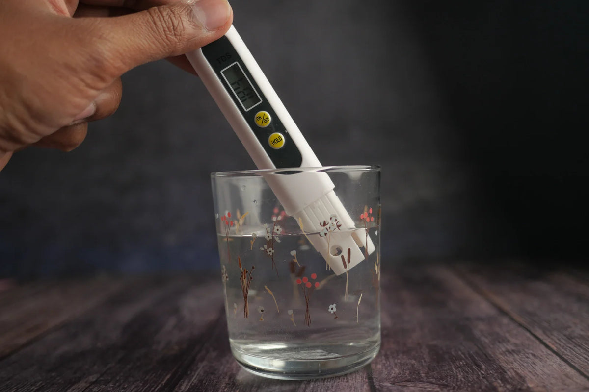
A TDS meter is your most important diagnostic tool. Test feed water and product water to calculate rejection rate:
Rejection % = [(Feed TDS – Product TDS) / Feed TDS] x 100
Healthy membranes reject 95–99%. If rejection drops below 90%, replace the membrane. Test every 6 months and after filter changes.
System Setup and Compatibility
RO systems come in various configurations. Knowing your setup helps with upgrades and replacements.
Common RO Stage Configurations
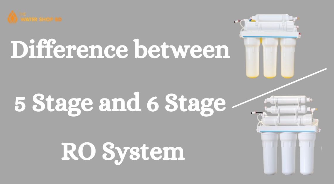
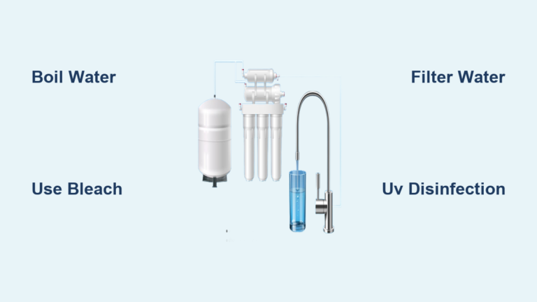
• 4-Stage: Sediment → Carbon → RO Membrane → Post-Carbon
• 5-Stage: Adds a second sediment or carbon filter for better pre-filtration
• 6-Stage: Includes specialty media like alkaline, remineralization, or quantum disinfection
Most filters follow the 2.5″ x 9.75″ standard, making replacements widely available. Always verify compatibility with your model (e.g., APEC, iSpring, Watts).
Booster Pump Applications
If your water pressure is below 40–60 PSI, consider a booster pump. These 120V pumps (e.g., Aquatec 5800) increase feed pressure for faster production and higher efficiency. They’re essential for tankless RO systems and commercial units.
Include a pressure switch and transformer for automatic operation.
NSF Certification Standards
Look for parts certified to:
• NSF/ANSI 58: Reverse osmosis systems
• NSF 42: Aesthetic effects (taste, odor)
• NSF 61: Health effects (lead, chemicals)
Certified components ensure safety, performance, and compliance. “American-made” parts often meet these standards with domestic manufacturing.
Troubleshooting Common RO Issues
Use this guide to diagnose and fix the most frequent problems.
Continuous Drain Flow Fix
If water runs nonstop to the drain, the ASO valve or flow restrictor is likely faulty. First, check if the tank is full. If not, the ASO may be stuck open. Replace the automatic shutoff valve.
Also verify the flow restrictor matches your membrane’s GPD rating. A missing or incorrect restrictor causes constant flow.
Low Tank Pressure Solution
A weak stream from the faucet often means low tank pressure. Shut off the water, open the faucet to drain the tank, then check the air valve at the bottom. Inflate to 5–7 PSI with a bike pump.
If water sprays out, the bladder is broken. Replace the tank.
High TDS Water Causes
If purified water tastes bad or has high TDS, the RO membrane is failing. Test both inlet and outlet TDS. Less than 90% rejection means it’s time to replace the membrane.
Also check for bypass leaks in fittings or a failed check valve.
Fixing Leaking Fittings
Leaks usually stem from dry, cracked, or misaligned O-rings. Shut off water, depressurize, and inspect all seals. Lubricate with silicone grease and reseat.
If the leak persists, replace the O-ring or fitting. Ensure tubing is fully inserted into quick-connects.
Frequently Asked Questions About Reverse Osmosis System Parts
What is the most important part of a reverse osmosis system?
The RO membrane is the most critical component. It removes up to 99% of dissolved solids, including salts, heavy metals, fluoride, and nitrates. Without a functioning membrane, the system cannot produce purified water regardless of how well the other parts work.
How often should I replace RO system filters?
Pre-filters (sediment and carbon) should be replaced every 6–12 months. The post-carbon filter needs replacement every 12 months. The RO membrane lasts 3–5 years, depending on feed water quality and pre-filtration maintenance.
What size flow restrictor do I need for my membrane?
Match the restrictor to your membrane’s GPD rating:
• 18 GPD → 150 ml/m
• 50 GPD → 420 ml/m
• 75 GPD → 550 ml/m
• 100 GPD → 800 ml/m
Using the wrong size causes poor water quality or excessive waste.
Why does my RO tank pressure keep dropping?
Low tank pressure usually means the air pre-charge is below 5 PSI. Check the air valve at the bottom of the tank with a tire gauge and inflate to 5–7 PSI using a bike pump. If water sprays from the valve, the internal bladder is ruptured and the tank needs replacement.
Can I use Vaseline on RO system O-rings?
No. Never use petroleum-based lubricants like Vaseline on RO O-rings. Petroleum degrades rubber and voids NSF certifications. Use only food-grade silicone lubricant (NSF-61 certified) to maintain seal integrity and prevent leaks.
Do I need a booster pump for my RO system?
If your feed water pressure is below 40–60 PSI, a booster pump is recommended. Pumps like the Aquatec 5800 increase production speed and efficiency. They’re also essential for tankless RO systems that require higher flow rates.
Key Takeaways for Understanding RO System Parts
A reverse osmosis system is only as strong as its weakest part. By understanding the parts of a reverse osmosis system, from pre-filters to faucets, you can maintain peak performance and extend component life.
Three critical points to remember:
• Replace filters on schedule to protect the membrane
• Test TDS every 6 months to monitor membrane health
• Keep spare O-rings, silicone grease, and basic tools on hand
Your next step: Pick up a TDS meter if you don’t already have one. Test your feed water and product water today to establish a baseline. This simple measurement tells you exactly when your membrane needs replacement and helps you catch problems before water quality suffers.